
You can also follow us on Facebook and Twitter to receive daily updates. If you liked this article, then please subscribe to our YouTube Channel for PLC and SCADA video tutorials. These 7 segment displays are driven by specialized chips like CMOS 4511, TTL 7447, etc. But, a resistor needs to be used for protecting against higher current out of range.

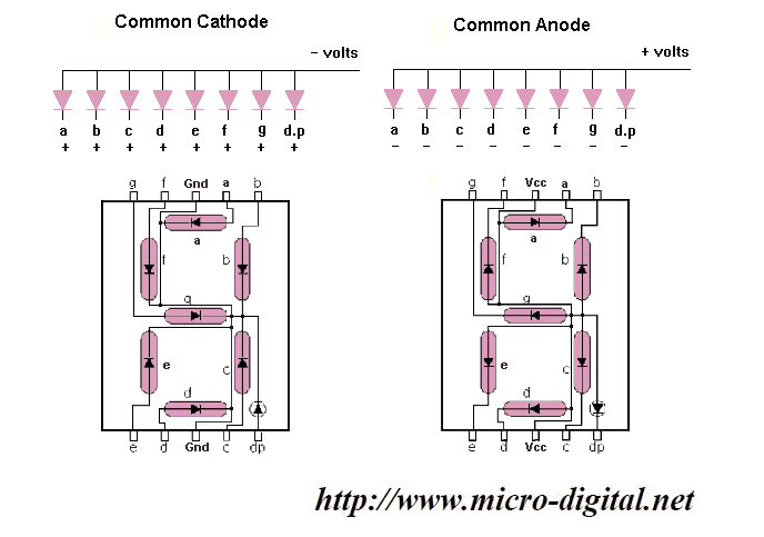
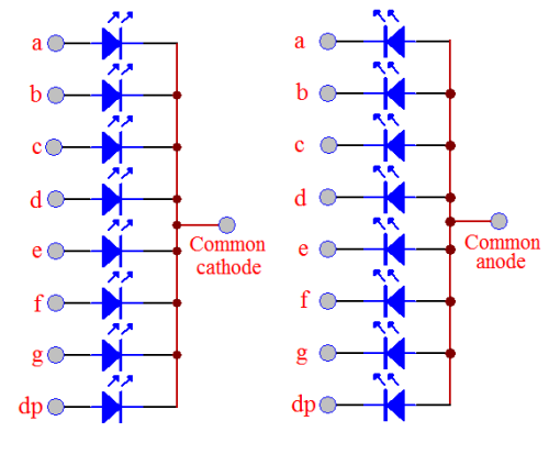
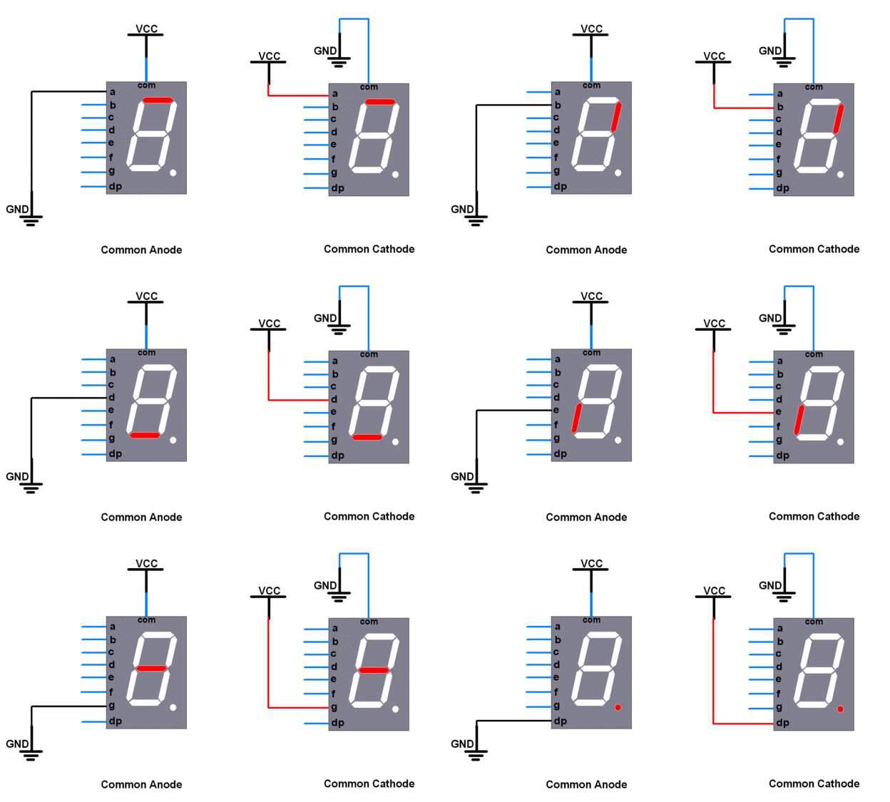
The amount of light emitted depends on the forward current applied. Out of both, the common anode is the mostly used ones as logic circuits can sink more current than they source. So, if you want to display 2, simply energize the LED’s – a, b, g, d, e. So, in the CA display, LED glows when we apply a negative potential to the selected diode and in the CC display, LED glows when we apply a positive potential to the selected diode. It is important to use a resistor in series with supply voltage otherwise, the circuit can be damaged due to over-current. In the common cathode type, the common voltage of 0V is applied to all the diodes.ĭepending upon the logic, the corresponding +5V is given which power-ups the diode, and light is emitted from it. either all the anodes or all the cathodes they will end up with an excess of wires. In common anode type, the common voltage of +5V is applied to all the diodes.ĭepending upon the logic, the corresponding 0V is given which power-ups the diode and light is emitted from it. The words common-anode and common-cathode are often new terms which. As discussed earlier regarding powering the diodes, this type of display can be categorized into two types – As you can see, there are 7 lines (means 7 diodes) arranged in such a way that when lit up, the corresponding number will be shown. Use this one LED for three status indicators or pulse width modulate all three and get mixed colors Note: The datasheet below is for the common cathode version. To show a particular number, the corresponding LEDs arranged in the matrix are energized to brighten that part and show the number.īelow is the figure describing it. Due to its design, all the numbers from 0 to 9 can be shown on that. The 7 diodes are energized through programming written inside the chip.


The color of the light depends on the type of semiconductor material used to produce the diodes. When these diodes are forward biased by an external voltage, the emission of photons occurs from them. 7 Segment LED DisplayĪ 7 segment display consists of 7 light-emitting diodes or LED’s. Many of the products use these types of numeric displays. Be it a timetable on the railway platform, digital watch, displays in automobiles, washing machine displays, etc. Hopefully, this has helped you work out what type of display you've got, and now you can get back to business.7 segment LED displays are one of the most widely used displays in various sectors. Below is a graphical diagram that shows the standard letter assigned to each of the segments and a very common wiring arrangement. Common Cathode Common Cathode displays have all the LED cathodes connected together and need a driver with outputs that become high to turn each segment on. Pinouts used for most 7segment displaysįor most displays, the wiring will look somewhat like the example. Common Anode displays have all the LED Anodes connected together and need a display driver with outputs which become low to turn each segment on. If your display is common ANODE, then you'll have to reverse the logic when you write to it, as a HIGH value will be OFF, and a LOW value will be ON. You can check all segments are working using the same technique, just connect to each of the A-G pins in turn (using the correct polarity of course). If the LED has not lit up in either example then it is potentially broken. So swap the two wires over on the battery or supply, if the LED lights up now it is common CATHODE. If no segment lights up then you need to reverse the wiring. If the LED lights up, it is common ANODE. Next, connect the resistor to the positive terminal (either battery or supply) and then connect any of the A-G segments to 0V or GND. This will avoid potential damage to the LED's in the display. This is easily done with a low voltage supply (9V or less) from a battery, bench PSU or Arduino board.įirstly and before anything else, connect a 1K resistor between the common pin and the battery. If you've got a 7 segment display but are not sure if it is common anode or common cathode, then you need to check the polarity of the display.


 0 kommentar(er)
